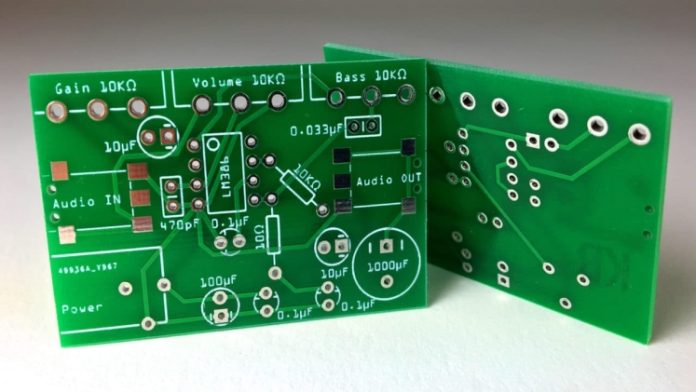
To follow the steps in the PCB layout tutorial, you will need Workspace. You should activate Workspace and install sample data, as well as create a new project. To capture the schematic, you need to create a PCB project.
Creating a PCB layout
If you have ever wanted to learn how to create a PCB layout, you will appreciate this tutorial. The PCB itself is an important piece of electronics design. It is comprised of two basic sides, the top and the bottom. Some PCBs also have a layer between them. In this tutorial, you will learn the basics of PCB layout and its construction. After completing the tutorial, you will be able to create your own PCB.
During the PCB layout process, you must first determine the design goals. It should be based on a schematic or design. Using the schematic will help you determine the board’s shape, routing, and layers. It is also important to remember that sensitive signals should not cross any of the planes. Otherwise, they may cause noise on the board. You will want to use the same layer configurations as you would for a double-sided PCB, including the separation of signal and ground planes.
Once you’ve figured out the design goals, you can begin selecting components. Selecting components and connecting wires are the next steps. Once you have decided which components you want to include, you can create the PCB layout. Then, you’ll need to define the connection between them. Next, you’ll want to define the power and ground planes. You’ll also want to connect the components. You’ll want to make sure the tracks are routed correctly, too. Once you’re satisfied with the layout, you can export the Gerber files to a PCB manufacturer.
Creating a Drill file for a PCB layout
NC Drill Files are also known as numeric control drill files. They regulate the size and location of holes and tooling for PCBs. PCB designers and engineers need this file to send their designs to a PCB manufacturer. Some engineers send the files directly to the PCB manufacturer for drilling. Regardless of how you create your drill files, it is essential to create one.
To create a NC Drill file, use a PCB design software that supports exporting Gerber Files. Gerber Files contain a variety of data, such as layers, layout, and drill holes. These file formats are used to design PCBs. There are also different file formats used by PCB layout software. Some of them, such as Cadence AWR, have a separate native file format.
Ordering a PCB
Once you have a PCB design, you will need to order it to get it manufactured. A PCB manufacturer will provide you with a PCB at a low cost, and they will manufacture it without the need for chemicals. You can upload your Gerber file. The next step in the process is to determine which components are on the PCB. First, place any fixed-location components, like connectors. Next, select the auxiliary components, such as crystals, decoupling capacitors, and series resistors. Use the mouse to determine their placement, and the ESC key to exit placement mode. If you’re unsure of the placement or size of the components, don’t worry, you can change the size and color of them with the right mouse click.
After you’ve selected your PCB design, you can order the PCB layout tutorial from a provider. Most companies offer these services to help you create a custom PCB layout. The process begins with the creation of a schematic, or a concept block diagram. A schematic consists of component symbols and the net connections between them. When your schematic is finalized, your PCB layout will be ready for production.

